
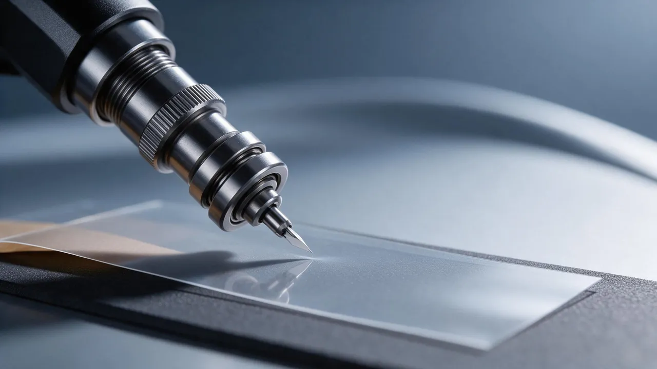
Short answer: Blade extension, offset and cutting force are important setup variables, together with speed, media feeding and tool condition. Verify them with a test cut on the actual film and liner. Correct extension can resolve some faults, but no percentage of failures is established here.
A cutting plotter separates material along a toolpath. For lined adhesive film, setup must account for the film, adhesive and release liner. Incorrect settings can appear later as difficult weeding, a damaged liner or a torn edge. Follow the equipment instructions when handling the blade and performing tests.
This guide covers blade selection, test cuts, offset, force and maintenance records. Its numerical examples are not universal PPF settings; the actual machine, tool and film instructions take priority.
On this page
How the blade works
A drag knife swivels as the cutting direction changes. Its cutting tip is offset from the rotation axis, so the controller must use the appropriate compensation for the installed blade. Incorrect compensation can distort corners; it is not the only possible cause.
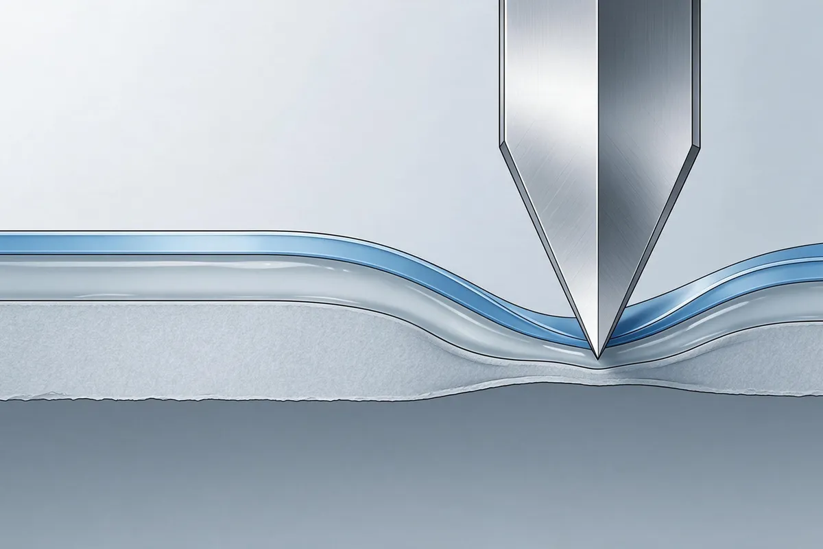
Blade extension is the amount protruding from the holder. Distinguish these two cutting modes:
- Kiss cut — cuts the intended film and adhesive layers while preserving the liner as a usable backing. Confirm the machine's specified test result rather than assuming any liner mark is acceptable.
- Through cut — separates the full material stack. Use only a through-cut method supported by the equipment and its carrier or cutting surface.
Kiss cutting separates the film while leaving the liner intact. Inspect both the cut edge and the liner when setting blade exposure and force.
Blade types and angles
| Blade | Selection consideration | Application to verify |
|---|---|---|
| 45° standard | General-purpose option in some tool ranges; compatibility and life vary | Use for PPF only when approved for the actual film and machine |
| 60° | May suit thicker media in a manufacturer's blade range; not universally a stronger tip | Confirm blade, holder, permitted force and test-cut quality |
| 30° | Trial-fit the exact vehicle, body panel and film. Record the trim version, usable edge return and final fit before cutting a production batch. | Verify suitability for the detail size and media, not a universal thin-film recommendation |
| Carbide versus steel | Edge life depends on blade grade, geometry and use | Choose compatible consumables for the required production conditions |
Wear can reduce cut quality, but there is no universal replacement distance. Inspect test cuts and track wear under the actual material and workload.
Adjusting extension with a test cut
Use the equipment's adjustment procedure and verify the result on scrap. A visual estimate or holder scale alone does not confirm a satisfactory cut.
- Load scrap from the intended film and batch using the equipment's specified media orientation and support.
- Run the machine’s test cut on a scrap of the actual film. Use shapes that test straight lines, curves and the smallest detail in your pattern.
- Check whether the unwanted film separates cleanly without pulling or damaging the intended pattern.
- Inspect the liner against the machine's criteria. Do not accept a cut-through liner for an intended kiss cut; the acceptability of surface traces depends on the specified process.
- Check separation of the intended layers. Difficult release or liner tearing can have several causes; inspect extension, force, blade condition and media handling rather than assigning one cause from the symptom alone.
Recheck after a blade change and when changing rolls, films or conditions, as required by the equipment and quality plan. A previous setting is a starting record, not proof that the next roll will cut correctly.
Offset and corners
Offset is the distance between the rotation axis and blade tip. A value unsuitable for the blade can round corners or produce protrusions. Use the specified blade value and the machine's test procedure before adjusting compensation.
| Symptom | Possible cause to check | Check or adjustment |
|---|---|---|
| Rounded outside corners | Offset may be too low; check tool and controller settings | Verify the specified offset and retest; adjust only within the machine's procedure |
| Spikes or loops at corners | Offset or holder condition may be unsuitable | Check offset, correct seating and free blade rotation |
| Ragged or frayed cut edges | Blade wear, force, extension or media handling may contribute | Inspect the blade and test the specified conditions; do not simply increase force |
| A shape remains partly uncut | Possible feed, material lift, static, speed or tool issue | Check loading, support, cleanliness and the machine's troubleshooting procedure |
| Liner cut through | Excess extension or force, or an unsuitable mode, may contribute | Stop and reset the intended kiss-cut conditions, then test again |
Cutting force and speed
Cutting force is a force setting, not pressure per unit area. Too little or too much can impair the cut, depending on the blade, material and support. Keep settings within the equipment's permitted range.
Start with the machine and film settings, then adjust one variable at a time. Check the displayed units and inspect a test cut before cutting the full pattern.
Record the machine, blade, film, batch and tested settings in an accessible job record. A label may help identification but does not replace the equipment procedure or quality record.
Thickness, construction and temperature can affect cutting. Do not assume that thicker film always needs more force or that force should always be changed before extension. Cold material may become stiffer; confirm its specified conditioning and operating conditions before testing.
Maintenance and stability
Maintenance is one possible source of changing cut quality, alongside settings, media and machine faults. The following is a source planning checklist, not evidence that four items explain nearly all failures.
| Item | Source interval example; equipment instructions control | Possible effect if unsuitable |
|---|---|---|
| Cutting strip | Source suggests weekly rotation; rotate or replace only as the machine allows | Uneven support can affect cutting across the sheet |
| Blade | Log use and inspect quality; no universal meter-based life | Wear may cause ragged edges or other cutting faults |
| Pinch rollers | Source suggests weekly cleaning and monthly tension checks; follow the specified method and interval | Contamination or unsuitable feeding can cause skew or tracking errors |
| Blade-holder seating | Check at each blade change using the equipment procedure | Incorrect seating can impair accuracy or damage the tool |
Log blade changes, dates, material and usage. Compare changes in test-cut quality with those records before attributing a fault to a single setting.
Interpreting symptoms
Weeding and test patterns provide useful clues, but they do not establish a single cause. Use the machine's fault-finding procedure and inspect the material and tool together.
- Difficult weeding and a torn edge. Check incomplete cutting, blade wear, force, extension and media condition. Do not diagnose extension alone from this symptom.
- The liner lifts with the cut pattern. Inspect the liner for damage and check the cut mode, extension, force and separation method. The symptom alone does not establish a specific bond failure.
- A straight cut has wavy edges. Check feeding, roller condition, material movement, tool seating and relevant machine settings; do not automatically exclude the blade.
- The same pattern fails at the same location. Check the cutting surface, media feeding and the file or toolpath at that location. A worn strip is one possibility, not a proven diagnosis.
Inspect and service the cutting strip as specified. Grooves or uneven support may affect effective cutting depth; compensating with more blade extension can create other problems.
Frequently asked questions
How often should a plotter blade be replaced?
Follow the tool supplier's guidance and monitor test-cut quality under actual use. Record material, workload and quality so replacement is based on evidence rather than a universal distance.
Why does the plotter cut through the liner?
Excess extension or force, an unsuitable cut mode or damaged support can contribute. Stop and use the manufacturer's adjustment and test-cut procedure. Do not prescribe one fixed adjustment order for every machine.
What is blade offset and why does it matter?
It is the distance between the rotation axis and cutting tip. A drag-knife controller compensates for it when changing direction. Use the value specified for the installed blade and verify corners with the machine's test routine.
Can clear and color films use the same settings?
Do not assume so. Actual thickness, liner, adhesive, topcoat and tool compatibility matter; a color name or metallic appearance does not establish construction. Test each specified film and record the successful conditions.
Why does a long pattern remain partly uncut?
Possible causes include material lift, static, speed, liner damage, feeding and tool condition. Check loading and support using the equipment's troubleshooting procedure before changing several blade settings together.
Does temperature affect cutting?
It can change material stiffness and cutting behavior. Cold stiffness is not chemical curing, and brittleness is not established for every film. Condition the material and equipment within their specified operating ranges, then test; do not rely only on a winter or summer label.
How can lifting at cut corners be investigated?
Check the pattern, cut quality, handling and material instructions. Do not automatically add bleed, increase force or wait for an undefined settling period. Any pattern allowance or handling change needs validation for the product and intended fit.
Should the liner face up or down?
Use the orientation specified for the equipment and film. For a conventional kiss cut, the intended film and adhesive layers are cut while the liner remains usable; do not treat cutting from the liner side as a general rule. Through cutting, reverse cutting and carrier-sheet workflows need their own approved procedure.
How can patterns exceed the machine's working area?
Use only supported feeding or sectional-cut workflows. Agree any seam or overlap before production and confirm the final fit. Do not assume a longer bed is required for every roll-fed machine, or prescribe trimming directly on vehicle paint.
Keep a verified setup record
Record the tested conditions for each film and tool, recheck after relevant changes and maintain consumables as specified.
For equipment sourcing alongside film, consult the OEM and ODM catalog and confirm the current machine, tool and software compatibility. For layout planning, see pattern cutting and nesting efficiency; for manufacturing context, see cast versus calendered TPU. To discuss a setup for your actual workload, contact our team.